This is not even close to the super cool Japanese Robo One robot competitions, but close enough. Sumobot competitions consist of a duel between two robots which have to push each other to make the other leave the arena. There are some specifications that must be followed such as dimensions and weight among others, but the rule is simple: the other robot has to leave the arena.

The arena is basicly a black circle within a white margin. This white margin is important because it will help the robot to know where the boundary is.
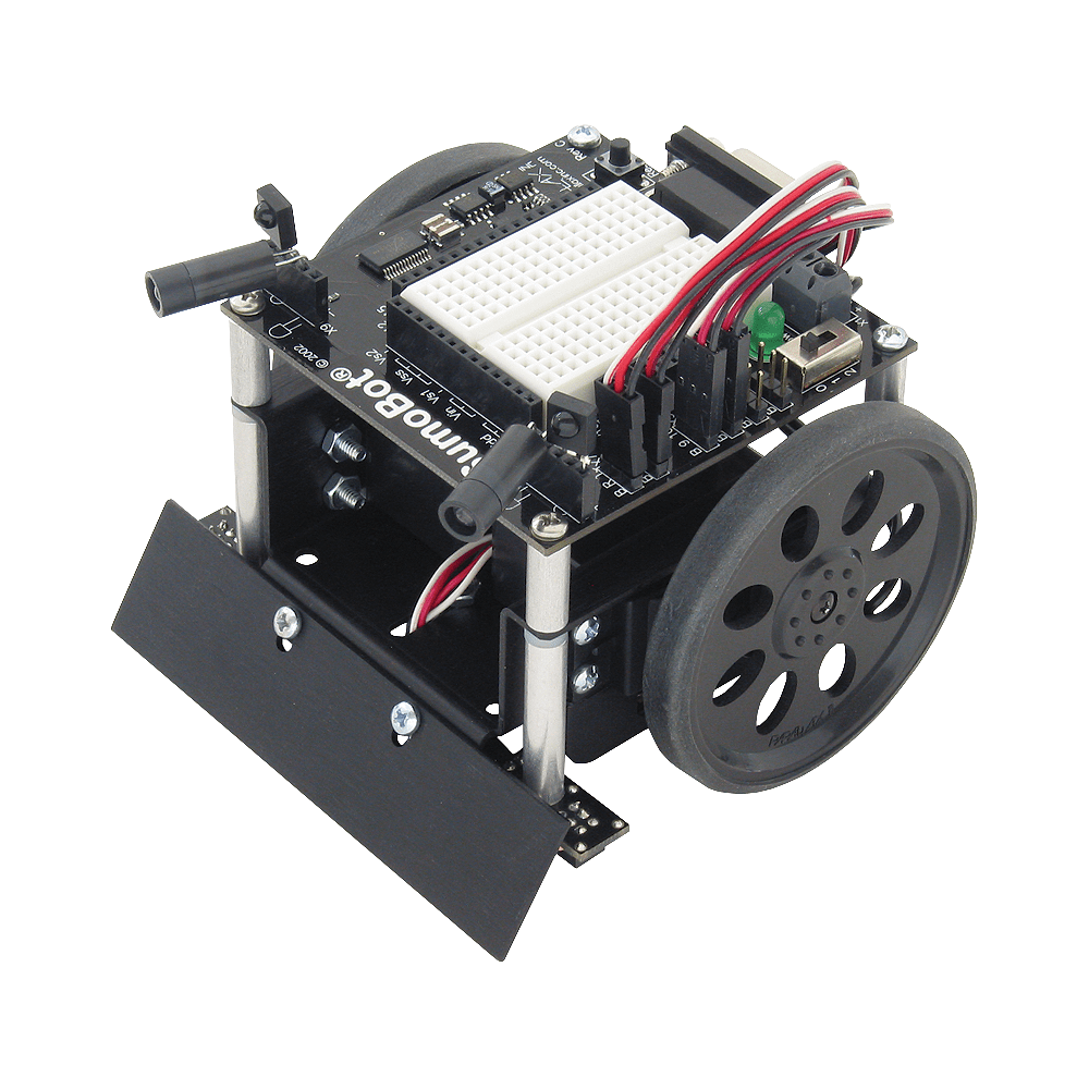
In our class we are using these robots which you have to build them up using components you can see there, called Sumobot. I would like to remark the most important parts:
- 2 Servo motors
- 2 Infrared LEDs
- 2 Infrared readers
- 2 QTI sensors (to detect the boundary)
By default, if we follow Sumobot’s instructions, we would use its serial port to transfer our programs to its core, but we’re using instead an AVR Butterfly (ATMega 169).
Servo motors are connected to timer counter 1 pins (ports PB5 and PB6) which will output the corresponding signal to make the wheels move.
QTI readers and Infrared readers are connected to other pins (PB0, PB1, PB2 and PB3). In case of QTI readers, when they detect white, the pin will be set to zero, otherwise it will be set to 1. In case of Infrared readers, when they detect an obstacle, the pin will be set to 0, otherwise it will be set to 1.
Infrared LEDs are connected to timer counter 0 pin (port PB4) which is set to a frequency of 38.5 KHz. This frequency is not arbitrary since the Infrared reader is only able to properly read reflected infrared signals under that frequency.